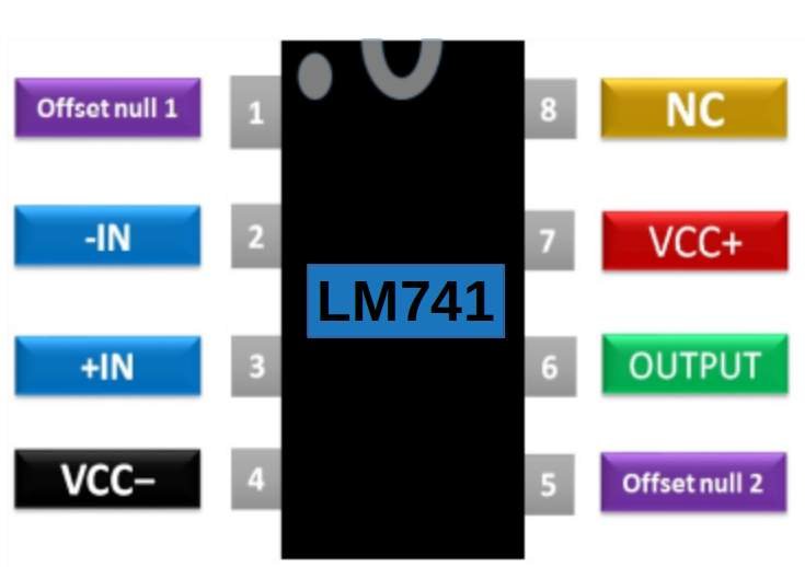
The basic operation of the LM741 is as a comparator. The LM741 also includes offset nulls for both the inverting and non-inverting inputs. Pinout for the LM741 from the LM741 datasheet published by Texas InstrumentsĪs the table indicates, the op amp has two power supply inputs that are at inverse polarity. However, all packages have eight pins that should be connected, as shown in the table below (from the LM741 datasheet published by Texas Instruments ). The LM741 op amp can be acquired in several different package types such as CDIP, PDIP, and TO-99. Making the Best Use of the LM741 Datasheet Let’s take a look at how the LM741 functions. Common Applications for the LM741 Op AmpĪs the list above shows, the device is often used for dual input applications however, the LM741 can also be implemented as a single input element by tying one of the inputs to ground. The LM741 op amp can be utilized in a wide variety of ways however, it is most often applied as listed below. Uses and Applications for the LM741 Op Amp Let’s investigate this component further using the LM741 datasheet. Notable characteristics are the large input impedance between the inputs and low output impedance. By far, the most commonly used op amp is the LM741, which is a general-purpose amplifier with two inputs-one non-inverting and the other inverting-and a single output. Typically, op amps are used as comparators or amplifiers and can be used as voltage sources for other devices or circuits. At some point, you may want to build up a dual 15V power supply.Among common electronic components, the operational amplifier, or op amp, stands out as one of the most often implemented parts and one of the simplest to utilize. Your device should be marked but if it isn't, I would take the worst case of the 3 devices. Note that there are 3 devices: LM741, LM741A and LM741C and they have different capabilities in terms of output voltage swing. Here is the datasheet: Every number is important. It's also worth noting, your batteries are a little low as the minimum supply voltage is +-10V for all variants. Remember, you can't get within 5V of the rails so your maximum signal swing is +-4V. Anything around 1 ufd up to 100 ufd will probably work at audio frequencies.

If my generator didn't swing around 0V I might have to put a capacitor in series with the signal.


I would put a 10k resistor in series with the signal to protect the op amp. Keep your signal generator output low at about 1V peak to peak until round two. Keep the gain to 1 until round two of your experiments. Use the voltage follower circuit you provided in Reply 3 with, say, 10k resistors. Now, connect the signal generator ground to this point.


 0 kommentar(er)
